The ThreatX WAF Sensor can be deployed behind a Google (GCP) Network Load Balancer for high availability. To facilitate HA deployment in GCP, ThreatX provides a .yml deployment template. The template may be used ‘as is’ or modified to help deployment into your particular GCP environment.
Introduction:
ThreatX WAF Sensors can be efficiently deployed in GCP environments. The ThreatX WAF Sensor can be implemented as a single instance or in a multiple-instance High Available (HA) configuration.
The ThreatX WAF Sensor image can be deployed behind a Google (GCP) Network Load Balancer for high availability. Use of a Network Load Balancer allows for architectures in which the client’s TLS (formerly SSL) session terminates at the ThreatX WAF. With the client’s session information being available to the ThreatX WAF Sensor, this architecture allows TLS client fingerprinting to occur.
A scaled ThreatX image Deployment within GCP creates a “Load Balancer sandwich” consisting of the ingress GCP Network Load Balancer, the ThreatX WAF Sensors deployed within autoscaling target groups, and the egress (to backend) load balancer or gateway depending on your specific origin architecture.
To facilitate HA deployment in GCP, ThreatX provides a .yml deployment template (and associated python files). This template is utilized through the use of Google’s command line SDK (gcloud). The template framework implements deployment to a greenfield VPC. The template may be used “as is” or modified to help deployment into your particular GCP environment.
The sensor-deploy.yml file, and other supporting files, can be provided by the ThreatX Security Operations Center (SOC) upon request.
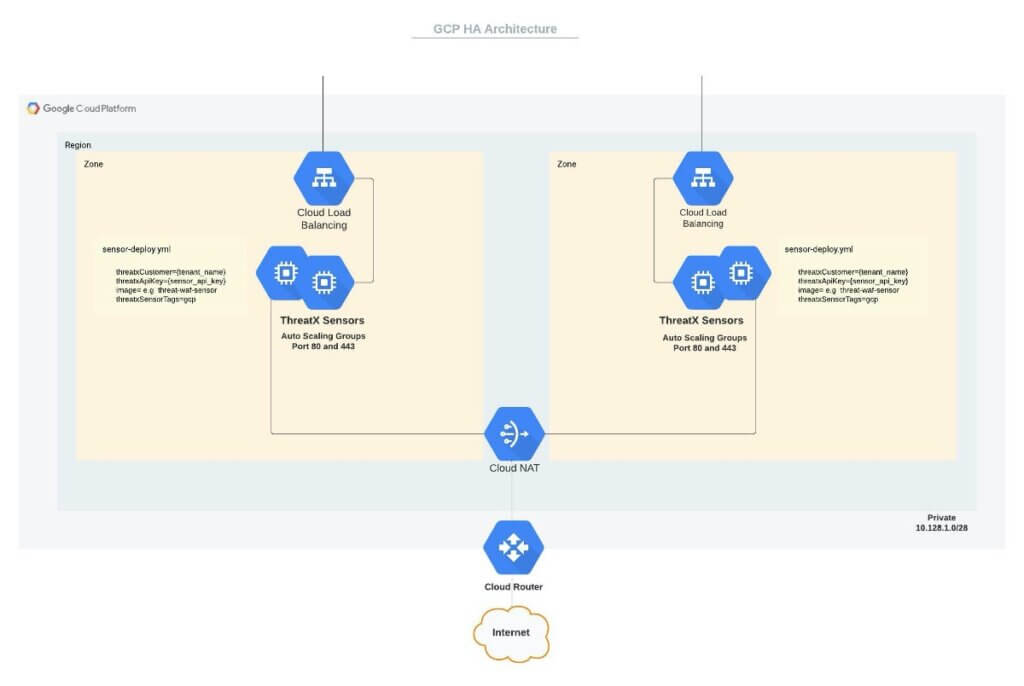
Note: Because origin server architecture may vary significantly and because the ThreatX deployment template does not deploy these backend systems, they are not reflected in Figure 1.
The deployment template parameters are customizable including the GCP network zones and ThreatX target group parameters; any specific network references in Figure 1 are simply for illustration.
There are several architectural components deployed with default template parameters. These resources are described below:
Network Load Balancer
The two Google Network Load Balancers will provide ingress to defined target groups of ThreatX WAF Sensors. A NLB will be available in each respective zone and utilize (public internet-facing) permanent IPs (not explicitly shown in Figure 1) created by the deployment stack.
The NLB can preserve the client IP and allow the client TLS (aka SSL) to terminate at the ThreatX WAF Sensor instead of at the load balancer. As noted in the introduction, an NLB acting as a TCP load balancer allows the ThreatX WAF Sensors to utilize IP interrogation and TLS fingerprinting techniques fully.
Target Pools
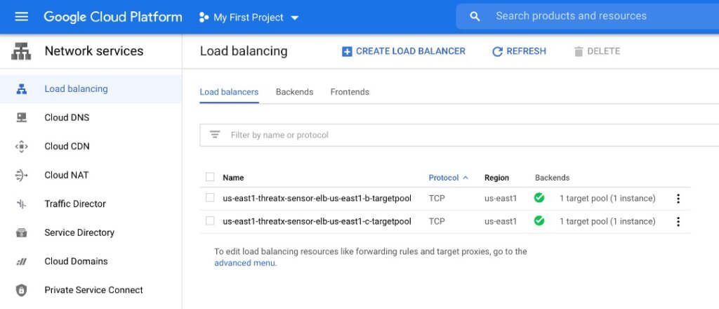
The ThreatX WAF Sensors will be deployed in two target pools corresponding to the NLB zones. These two target pools are distributed across zones for fault tolerance. The target pool mapping to the instance group manager and instances is shown below:
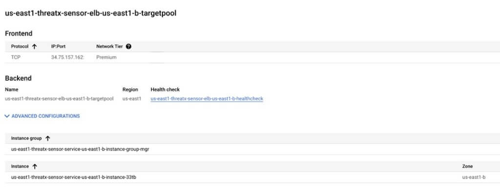
Please note that, as shown in Figure 3, a healthcheck is also configured, in each zone, by the deployment script. Instance groups as well as instance templates will be setup in each zone. This is illustrated below.
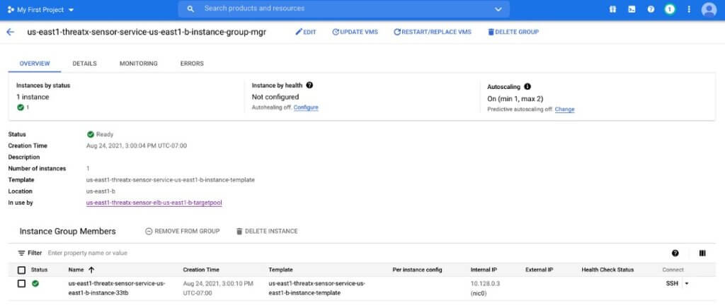
The defined instance template (seen in Figure 4) utilizes a default VM instance type of f1-micro. It is recommended this be changed (in sensor-deploy.yml) to e2-medium for most production deployments.
An autoscaler group in each zone is also created. The default pool has a minimum of 1 Sensor deployed (and a maximum number of 2 replicas). The number of replicas may be changed, again, via modification of the sensor-deploy.yml file.
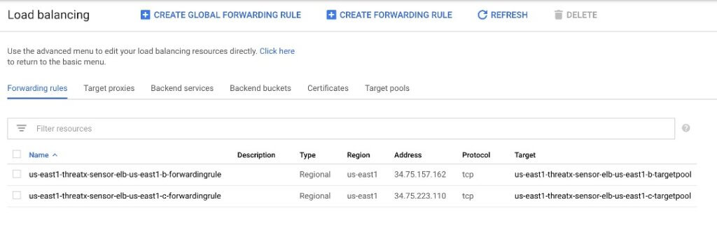
Forwarding Rules
Traffic forwarding rules for each NLB are also provisioned.
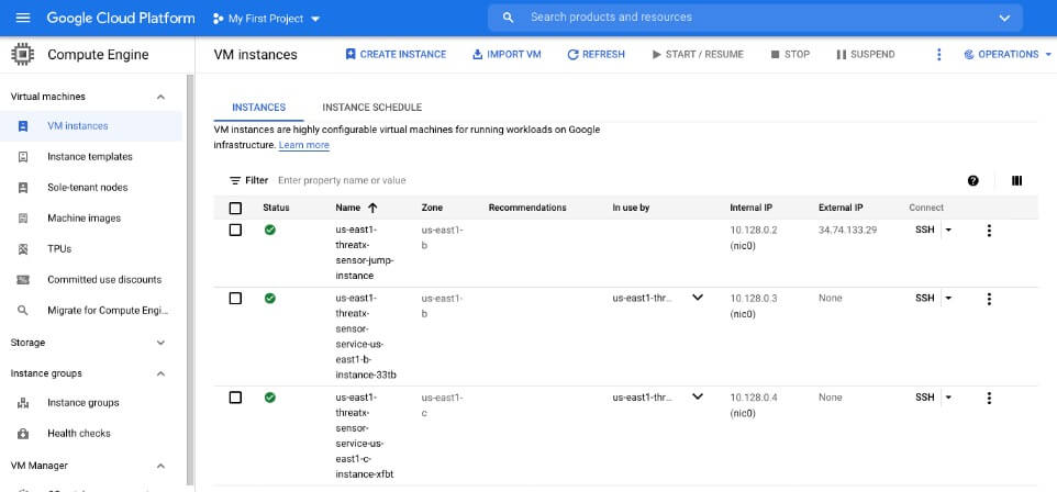
ThreatX WAF Sensors
The ThreatX WAF Sensor is available as a GCP image. The automation template will deploy VM compute instances in target pools.
Each ThreatX WAF Sensor must have Internet connectivity to the ThreatX cloud to the pull site, certificate, backend (i.e., origin), routing configuration, and security rules. Once the configuration is obtained, the ThreatX WAF Sensor will inspect and block (or tarpit, or interrogate) traffic, using configuration parameters pulled from the ThreatX cloud. If connectivity to the ThreatX cloud is lost, the ThreatX WAF Sensor will continue to operate using its most recent configuration. If connectivity to the ThreatX cloud is lost, event log messages will be locally cached until connectivity is restored.
The private IP space and NAT Gateway is utilized to enhance Sensor security.
In order to establish connectivity to the ThreatX cloud , both the tenant name and a Sensor API key must be obtained via the ThreatX management interface.
In Figure 1, this mandatory instance configuration information is shown in the “sensor-deploy.yml” callout. In addition to the ThreatX WAF Sensors, a bastion / jump host is deployed, as noted in Figure 6.
Network Infrastructure
The deployment stack creates multiple different networking components necessary to support the scaled ThreatX deployment. These components are described in more detail below.
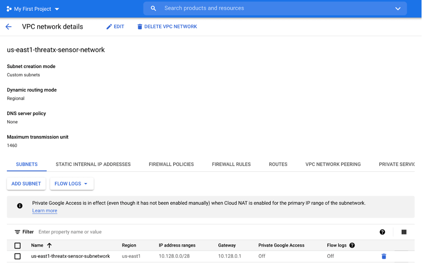
Network and Subnetwork
The deployment creates a network and a small subnetwork by default.
Gateways and Subnets
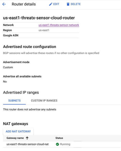
As noted above, the ThreatX WAF Sensors must communicate with the ThreatX cloud to obtain configurations. To provide a secure architecture, the private VPC subnets which house the ThreatX WAF Sensors communicate via NAT Gateway to ensure “one-way” communication. The Cloud NAT Gateway is a regional construct.
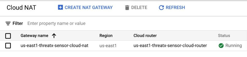
Cloud Router
A Cloud Router is also configured and associated to the Cloud NAT Gateway described above.
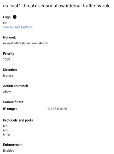
Firewall Rules
Rules will also be created by default to facilitate http(s) and allow for SSH management traffic to the target Sensors. Though SSH traffic rules are provisioned, during normal ThreatX WAF Sensor operation SSH access to the Sensors is not required. This access may be disabled / restricted as desired. The HTTP(S) and internal traffic provisioned firewall rules are shown below.
Practical Usage
Overview
In utilizing the deployment template, the stack creation process is relatively straightforward. ThreatX, upon request, can supply a package containing .yml file and several .py files as well as a README.md file. The README.md covers many of the deployment process execution steps shown below.
Obtaining the ThreatX Sensor image
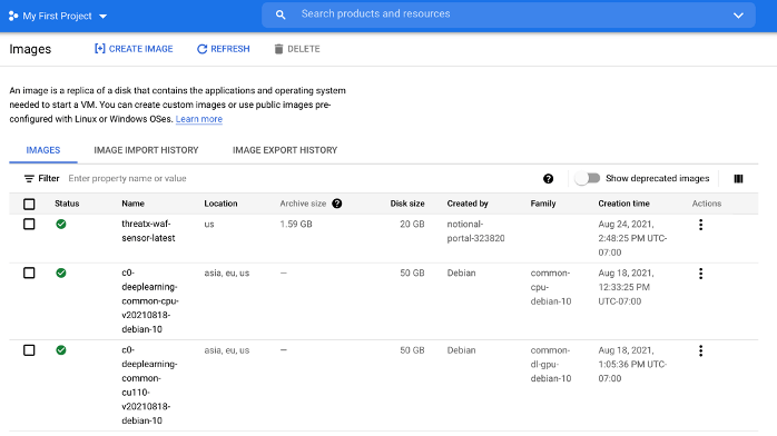
As documented, in the README.md, utilize the GCP SDK to create a ThreatX image in your Google project as shown below.

Here <user_project> is the Google project ID and will be a string without spaces (e.g. national-portal-513821)
Once successful, the ThreatX image should be present in your project as shown below.
Modifying the sensor-deploy.yml file
A sample deployment template, sensor-deploy.yml is shown below.
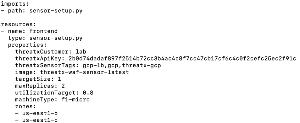
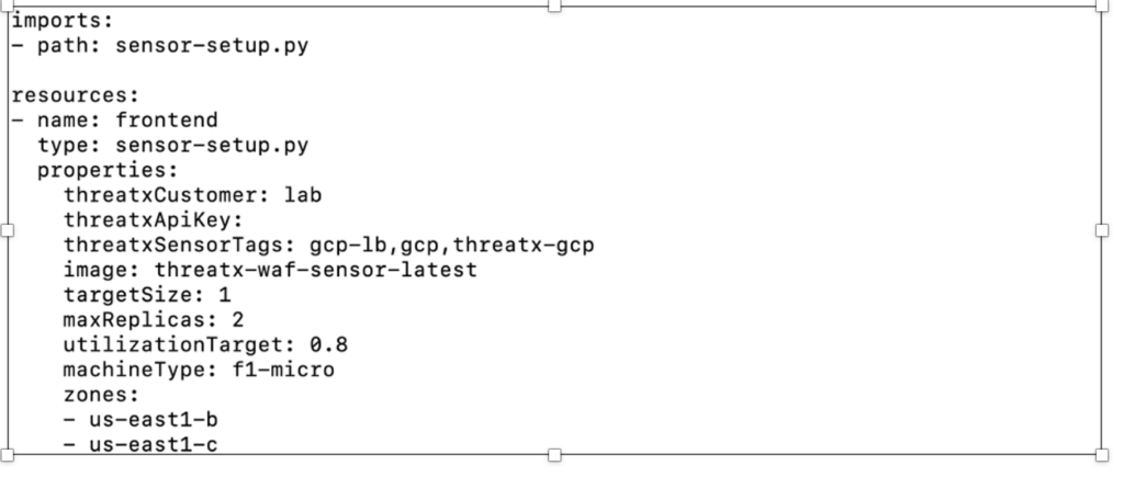
The parameter inputs are each briefly explained below each parameter. Where possible, the parameters are supplied with default values, which may be adjusted to meet your implementation requirements.
A few parameters may benefit from additional clarification:
- threatxCustomer: This is your tenant name and is found in the upper right corner of the interface after logging into Threatx. In the .yml file above the value of the parameter is “lab”.
- threatxApiKey: This also may be generated via the ThreatX interface, as shown below. It is a one-time generation of the key, so make sure to capture the value.
- threatxSensorTags: Optional standard GCP tags.
- image: The local project name of the ThreatX image garnered previously in “Obtaining the ThreatX Sensor image”.
Creating the infrastructure
Once the image has been obtained and the sensor-deploy.yml file has been appropriately modified , the ThreatX infrastructure can be created utilizing the Google SDK with the command in Figure 14 below.

Last Updated 2023-03-09